Drake Introduction 2 - Defining LeafSystems and Using Affine Systems
June 01 2022
(This is Part 2 of a planned series of posts on the robotic simulation library Drake developed by MIT and TRI. Part 1 is here.)
Objective
The goal of this article is to give an example of some useful concepts of Drake, specifically:
- AffineSystems
- LeafSystem Ports
- Pose of Rigid Bodies
We will connect the pose of our block to the state of a dynamical system and make the block turn in arbitrary directions.
Sketching Your Diagram
Let's think about the components that we will need for this example. We will add one "block" to our diagram from Part 1. The block will be a "Dynamical System".
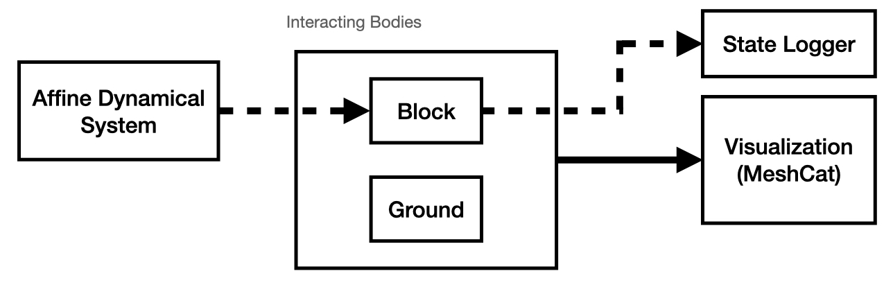
What we've added to the diagram is a block for an Affine Dynamical System.
We have most of the elements that we need from Part 1, so in order to create this Diagram in code we will:
-
Combine most of the elements from Part 1 into an abstraction called a
LeafSystem, -
Instantiate a simple Affine system and connect it to our
LeafSystem, - Finalize the Diagram and Simulate!
Lumping Our Previous Components into a LeafSystem
A LeafSystem in Drake can be thought of as a block in your Diagram with inputs that can transform those inputs into some set of outputs.
(I know this is a very vague description.)
You could create a LeafSystem that:
- Computes the output of a differential equation based on a forcing input (seems unnecessary since Drake can do this for any body),
- Computes the output of a parameterized optimization problem where some parameters of the optimization problem are given as inputs (so they're only known at runtime), or
- Estimates the poses of objects in the world based on using OpenCV on images collected in real-time.
Consider the following definition of a BlockHandlerSystem which will inherit all of the methods and properties of LeafSystem (i.e. LeafSystem is the base class of this new system).
Initializing the BlockHandlerSystem()
class BlockHandlerSystem(LeafSystem):
    def __init__(self,plant,scene_graph):
        LeafSystem.__init__(self)

        # Constants
        self.block_name = 'block_with_slots'

        # Add the Block to the given plant
        self.plant = plant
        self.block_as_model = Parser(plant=self.plant).
            AddModelFromFile(
                "/root/OzayGroupExploration/drake/manip_tests/slider/slider-block.urdf",
                self.block_name) # Save the model

        AddGround(self.plant) #Add ground to plant

        # Add the Triad
        self.scene_graph = scene_graph
        AddMultibodyTriad( plant.GetFrameByName("body"), self.scene_graph)

        self.plant.Finalize()
        self.context = self.plant.CreateDefaultContext()

        # Create Input Port for the Slider Block System
        self.desired_pose_port = self.DeclareVectorInputPort("desired_pose",
                                                                BasicVector(6))

        # Create Output Port which should share the pose of the block
        self.DeclareVectorOutputPort(
                "measured_block_pose",
                BasicVector(6),
                self.SetBlockPose,
                {self.time_ticket()}   # indicate that this doesn't depend on any inputs,
                )                      # but should still be updated each timestep
As we discussed earlier, this system contains most of the components that we've already discussed in Part 1 (block_as_model,AddGround(),plant.Finalize(), etc.).
But, let's take a moment to discuss some of the new additions:
-
self.desired_pose_port: This is a port that our system receives as input and is named "desired_pose". As the name states, it will tell us the desired pose of our "block_with_slots". -
"measured_block_pose": This output port is meant to share the measured pose of the block with anything connected to it.
Note that this is important if we would like to log the block's pose with a Logger (as was done in Part 1).
Also, note the following input to
DeclareVectorOutputPort():self.SetBlockPose. This is the function that is called whenever we want to compute the output of thisBlockHandlerSystem. We will talk more aboutself.SetBlockPose()next. -
AddMultibodyTriad(): This function adds a visual element to the scene: A triad representing the pose of the frame that was used to define it. This function is INCREDIBLY helpful while debugging. It is not currently available in Drake, but you can look at this file on Github to obtain a copy.
Computing the BlockHandlerSystem's Output: SetBlockPose()
def SetBlockPose(self, context, output):
    """
    Description:
        This function sets the desired pose of the block.
    """

    # Get Desired Pose from Port
    plant_context = self.context
    pose_as_vec = self.desired_pose_port.Eval(context)

    self.plant.SetFreeBodyPose(
        plant_context,
        self.plant.GetBodyByName("body", self.block_as_model),
        RigidTransform(RollPitchYaw(pose_as_vec[:3]),pose_as_vec[3:])
    )

    self.plant.SetFreeBodySpatialVelocity(
        self.plant.GetBodyByName("body", self.block_as_model),
        SpatialVelocity(np.zeros(3),np.array([0.0,0.0,0.0])),
        plant_context
        )

    X_WBlock = self.plant.GetFreeBodyPose(
        plant_context,
        self.plant.GetBodyByName("body", self.block_as_model)
    )

    pose_as_vector = np.hstack([RollPitchYaw(X_WBlock.rotation()).vector(), X_WBlock.translation()])

    # Create Output
    output.SetFromVector(pose_as_vector)
This uses much of the machinery from Part 1, but I will add a few additional notes:
-
The function
SetBlockPose()must accept the three arguments:self,context, andoutput. This is required as a function associated with an output port. -
pose_port: We collect the current pose input given to the system by calling.Eval(context)on our pose port. The context input is important and probably deserves its own discussion. I will say, for now, that it is primarily important that this context is the context that is given as an input toSetBlockPose(). -
output.SetFromVector(pose_as_vector): When done making your computations, make sure to set the value of the output port using this function!
Defining the Initial State of the BlockHandlerSystem: SetInitialBlockState()
This is very similar to how we set the initial pose in Part 1 of this introduction series. We will include the code below in an appendix, but will not discuss it in detail here.
Defining An Affine Dynamical System
Broadly speaking, dynamical systems are models of how a quantity (like the pose of a robot) change over time. In this example, the model we will use is an Affine Dynamical System. As discussed in the Drake documentation's entry on AffineSystem, the model is described as:
\( \begin{array}{rl} \dot{x}(t) & = A x(t) + Bu(t) + f_0 \\ y(t) & = C x(t) + D u(t) + y_0 \end{array} \)
In words, the AffineSystem has some internal state \( x(t) \) which is governed by the affine equation above. The output of the system (and thus the output of the block) is \( y(t) \) which is an affine combination of the states and inputs. The input of the system is \( u(t) \).
We will avoid describing all of the elements in the system (you can play around with it to learn more). In our code, we simply want to change the value of the pose at a constant rate, so we will choose values to initialize the system such that the model will be:
\( \begin{array}{l} \dot{x}(t) = f_0 \\ y(t) = x(t) \end{array} \)
We will initialize such a system and connect it to our Diagram according to the sketch above with the following code:
# Connect System To Handler
# Create system that outputs the slowly updating value of the pose of the block.
A = np.zeros((6,6))
B = np.zeros((6,1))
f0 = np.array([0.0,0.1,0.1,0.0,0.0,0.0])
C = np.eye(6)
D = np.zeros((6,1))
y0 = np.zeros((6,1))
x0 = np.array([0.0,0.0,0.0,0.0,0.2,0.5])
target_source2 = builder.AddSystem(
    AffineSystem(A,B,f0,C,D,y0)
    )
target_source2.configure_default_state(x0)

command_logger = LogVectorOutput(
    target_source2.get_output_port(),
    builder)
command_logger.set_name("command_logger")

# Connect the state of the block to the output of a slowly changing system.
builder.Connect(
    target_source2.get_output_port(),
    block_handler_system.GetInputPort("desired_pose"))

u0 = np.array([0.2])
affine_system_input = builder.AddSystem(ConstantVectorSource(u0))
builder.Connect(
    affine_system_input.get_output_port(),
    target_source2.get_input_port()
)
Some additional notes about what is presented above.
- We encode that the six-dimensional pose vector (roll-pitch-yaw-x-y-z) is the state of the system.
- In this example, we choose to force the pitch and yaw to change with a constant rate of 0.1.
-
Once again, we use the builder to add this new object (a child class a.k.a. subclass of
LeafSystem) to the diagram. - An AffineSystem has a required input port for \( u_0 \) which is the input to the system. In this case, we make the input be a constant value of 0.2, but because the matrix \( B \) is zero, this input has no effect on the dynamics.
-
Port Connections:
To act as a sanity check, we connect the output of this affine system to the "desired_pose" port of the
BlockHandlerSystem, but we also connect it to a logger. The input port (as discussed above) is connected to aConstantVectorSourceblock to satisfy theAffineSystem's requirements.
Almost Done / Beware of Contexts!
Using what you've learned from the previous part, you should be able to put everything together (i.e. Build Your Diagram, Create Your Simulator, and run it) with one important caveat: The context of the built diagram must be shared with the block_handler_system. We do this here:
# diagram = builder.Build()
diagram_context = diagram.CreateDefaultContext()

# Set initial pose and vectors
block_handler_system.SetInitialBlockState(diagram_context)

meshcat.load()
diagram.Publish(diagram_context)


# Set up simulation
simulator = Simulator(diagram, diagram_context)
block_handler_system.context = block_handler_system.plant.GetMyMutableContextFromRoot(diagram_context)
To be honest, I'm still not completely sure of why this is the case, but the context that you give
to the SetFreeBodyPose() function is very important and it will not work if you don't provide
the diagram's final context to it.
This could be partially due to the fact that Drake doesn't want you to "override" the dynamics that its designers
have carefully created using their years of experience with Physics engines. Whatever the reason is, this step is critical!
Once again, for those working with Drake BE CAREFUL WITH YOUR CONTEXTS.
Putting It All Together
With the lines above as well as with the understanding that you've taken from Part 1, it should be possible to now create a video like the one shown at the beginning of this post. These elements are all combined in the script autonomous_slider_pose_changing.py on my GitHub, as well. Feel free to check it out to double check your understanding.
As usual, if you have any questions then feel free to send me an email or refer to the Drake documentation!
--
Appendix 1: SetInitialBlockState()
The following member function is included in the script connected to this walkthrough: autonomous_slider_pose_changing.py.
def SetInitialBlockState(self,diagram_context):
    """
    Description:
        Sets the initial position to be slightly above the ground (small, positive z value)
        to be .
    """

    # Set Pose
    p_WBlock = [0.0, 0.0, 0.2]
    R_WBlock = RotationMatrix.MakeXRotation(np.pi/2.0) # RotationMatrix.MakeXRotation(-np.pi/2.0)
    X_WBlock = RigidTransform(R_WBlock,p_WBlock)
    self.plant.SetFreeBodyPose(
        self.plant.GetMyContextFromRoot(diagram_context),
        self.plant.GetBodyByName("body", self.block_as_model),
        X_WBlock)

    # Set Velocities
    self.plant.SetFreeBodySpatialVelocity(
        self.plant.GetBodyByName("body", self.block_as_model),
        SpatialVelocity(np.zeros(3),np.array([0.0,0.0,0.0])),
        self.plant.GetMyContextFromRoot(diagram_context))