The Pusher Slider System
February 07 2021
The best way to learn how something works is to play with it; While you turn it around in your hands, try to find out how to break it, or just stare at it closely for a bit, it's secrets are slowly revealed. Unfortunately, for most robotic systems we aren't able to "play" as we normally might because real robots are too expensive to purchase frequently and most robotic simulators are complicated to use (usually requiring you to learn something like a simulator's API in addition to your programming language of choice).
This post is part of a proposed solution to this problem of play: It describes the Pusher Slider System one of the fundamental dynamical systems used in robotic manipulation. The system is simple, there is a small circle (the pusher) sliding on a 2D plane along with a square (the slider). The pusher's velocity can be exactly controlled, but the slider can only be moved by pushing against it with the pusher.
The System's State (It's Governing Physical Quantities)
The configuration of the system can be specified by four variables which are visualized in the picture below. The four quantities are:
- The x-coordinate of the slider (square) with respect to the coordinate system \( a\): \( s_x \)
- The y-coordinate of the slider (square) with respect to the coordinate system \( a\): \( s_y \)
- The orientation of the slider (square) with respect to the coordinate system \( a\): \( s_{\theta} \)
- The y-coordinate of the pusher (circle) with respect to the coordinate system \( b \): \( p_y \)
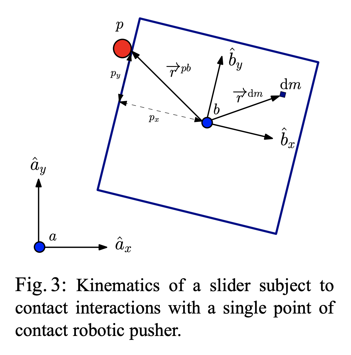
This image is taken from Feedback Control of the Pusher-Slider System: A Story of Hybrid and Underactuated Contact Dynamics by Francois Robert Hogan and Alberto Rodriguez.
Note that the position of the pushing object (circle) is not considered in the configuration. It is always assumed to be in contact with the edge of the slider and thus its x position relative to the coordinate frame \( b \) is constant. The pusher can still slide up and down the edge, but we assume that it never loses contact (which may be a strong assumption).
The System's Inputs (What Causes Motion)
What makes the system move is the choice of the pusher's motion \( \mathbf{u} = \begin{bmatrix} v_n & v_t \end{bmatrix}^\top \). We assume that the pusher is a disk whose velocity we can exactly control, but note that \( v_n \) and \( v_t \) are defined with respect to the sliders coordinate frame. So, the same "push" in the \(v_n\) component can result in different motions in the overall coordinate frame as shown in the images below.
Above is the observed effect of pushing "directly into" (i.e. \( v_n > 0, v_t = 0 \) the slider block at three different values of \( p_y \). (Left Panel) When the pusher is a bit to the left of the center of mass (\(p_y > 0 \) ), the slider turns to the right. (Center Panel) When the pusher begins immediately in line with the center of mass (\(p_y=0\)), then the slider slides straight forward. (Right Panel) When the pusher begins at a coordinate to the right of the center of mass (\( p_y < 0\) ), the slider turns to the left.
The Equations Of Motion
Whether or not the pusher (circle) slides along the side of the slider (square) is dependent on a complex interaction during pushing which we attempt to describe using the following equations of motion.
\( \dot{x} = \begin{cases} f_1(\mathbf{x},\mathbf{u}) & \mathbf{u} \in \mathcal{MC} \\ f_2(\mathbf{x},\mathbf{u}) & \mathbf{u} > \mathcal{MC} \\ f_3(\mathbf{x},\mathbf{u}) & \mathbf{u} < \mathcal{MC} \end{cases} \)
where \( x = \begin{bmatrix} \mathbf{q}_s^\top & p_y \end{bmatrix}^\top \), \( \mathbf{q}_s = \begin{bmatrix} x & y & \theta \end{bmatrix}^\top \) and \( \mathbf{u} = \begin{bmatrix} v_n & v_t \end{bmatrix}^\top \). The meaning of each of these values can be explained with the following image.
Problems I Ran Into
While writing this system there were some inaccuracies/problems that I ran into. Some of which I overcame, but some of which I still need help on (and would love an email with the solution, if you have it)! They are:
- [Solved] A typo in the formula for \( c \) in Feedback Control of the Pusher-Slider System: A Story of Hybrid and Underactuated Contact Dynamics. By inverting the formula they provide, I was able to create more realistic-looking motion.
- [Unsolved] Ambiguity in which friction constant to use in definition of the motion cone vectors of Feedback Control of the Pusher-Slider System: A Story of Hybrid and Underactuated Contact Dynamics. Which \( \mu \) goes in the equations (2) and (3)?
References Used
While I mainly used the first reference in this book for understanding, there was a formula (specifically the formula for \(c\) ), which was incorrect in the first reference and needed to be remedied by visiting the second source which contains the proper definition.